Posts

Showing posts from October, 2019

Slepian Theory

Image
Slepian Theory This also know as recovery rate theory. when arc is struck between electrodes or CB contacts, the medium between them is highly ionised. If current is alternating in nature,at current zero instant, the ionisation is very less (residual ionisation). After zero crossing, the ionisation again increases and the arc is restruck i.e. Arc current again increases. The voltage responsible for restricking of arc is known as restriking voltage. If dielectric strength of the medium is built up sufficient during current zero instant, it will prevent the arc to restrike i.e. current won't flow after that current zero instant.  This can be described as a race between dielectric strength and restriking voltage. If the rate of rise of dielectric strength is more than rate of rise of restriking voltage - the arc will not restrike.  But if rate of rise of dielectric strength is less than rate of rise of restriking voltage - the arc will restrike. The concept is elaborated

Minimum Oil Circuit Breaker (MOCB)

Image
Minimum Oil Circuit Breaker (MOCB) The supporting, current interrupting and top chamber are made up of porcelain. Hence, clearance between live parts and enclosure is small and requires less quality of oil, hence the breaker is called as Minimum oil circuit breaker (MOCB).  The chambers are completely filled with oil. The upper chamber of oil is does not come to lower. The fixed contact is enclosed in the quenching chamber. Moving contact makes sliding contact with lower fixed contact. The operating rod is operated by operating mechanism.the three poles are operating simultaneously. The voltage ratings are from 3. 6 kv to 420 kV.  Wnen the contacts carrying current are separated in the oil the arc is developed. The heat of arc causes decomposition of oil and gases are formed. These gases expand due to heating of arc. The gas flowing near the contact zone causes cooling and splitting of the arc and extinguishes the arc. After the arc is quenched at last curr

Fuses

Image
Fuses A fuse is a Short piece of metal inserted in the circuit, which melts when excessive current flows through it an thus breaks the circuit and protects the equipment.  Materials of fuse:- Most commonly used materials for fuse elements are lead, tin, copper, zinc, silver. Silver is used now-a-days. It is a best fuse material.   Important terms related to fuses:- Current rating of fuse element:-  It is the (r. m. s. value of) current which the fuse element can carry without over heating or melting. Fusing current:-  It is the minimum current at which the fuse element melts and disconnects the circuit protected by it. This value is obviously more than cuurent rating.  Fusing current depends upon the material of fuse element, length, diameter and type of enclosure.  The value is always greater than one. The smaller the fusing factor, the greater the difficulty in avoiding determination due to overheating And oxidation at reted curren

Induction type Over Current Relay

Image
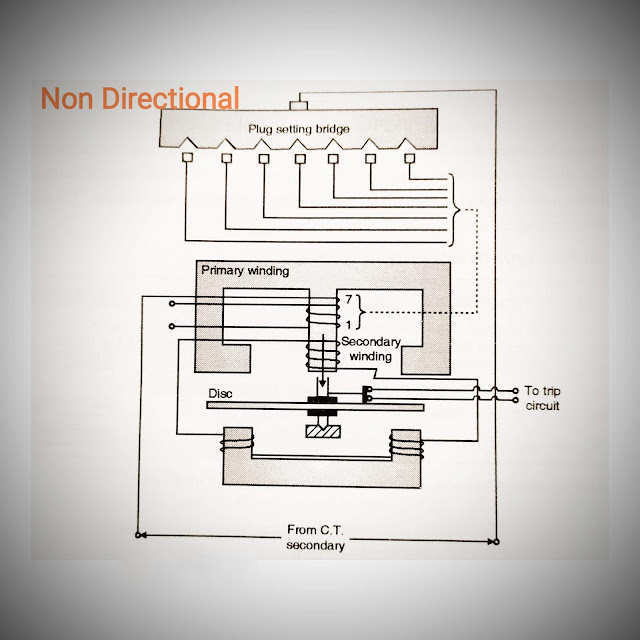
Induction type Over Current Relay Induction type Over Current Relay(Non Directional) :- Construction:- The relay works on induction principle. Actuating quantity is current (from CT secondary). The primary winding is connected to secondary of C. T. in the line to be protected. An aluminum disc is pivoted which moves freely between two electromagnets. The primary is tapped (1...... 7). Tne tappings are connected to plug setting bridge so that number of active turns on relay can be changed and desired current setting can be obtained. Secondary winding is connected to lower magnet by series connection. Due to induction principle e. m. f is induced in secondary due to current in primary. The torque exerted on the disc is due to interaction of eddy-currents in the disc and flux produced by upper and lower magnet. The two fluxes have phase displacement. The spindle carries moving contact which bridges the two fixed contacts which are connected to trip circuit. T

Desirable qualities And Term's of protective Relaying

Image
Desirable qualities And Term's of protective Relaying Selectivity and Discrimination Speed Sensitivity Reliability Simplicity Adequateness Economy 1. Selectivity and Discrimination:- Selectivity  is the ability of the protective system to select correctly the faulty part of the system and disconnect the faulty part without disturbing rest of the system. And in order to provide selectivity to the system entire system is divided into several protection zones.  Discrimination means 'identifying the difterence between'. This property of protective relaying enables it to distinguish between the nomaal condition and abnormal condition. The protective scheme should operate during abnormal condition and notduring normal condition. If Fault occurs at F1 the CB1 only should trip and other system continues to work. Similarly for F2 both CB3 and CB2 should open. Thus, the protective relaying should isolate only the faulty part of line without distu

Design of submersible motor

Image
Design of submersible motor Submersible pumps are immersed in liquid. A motor is coupled to the pump. Since this assembly (pump+mortor) is immersed in liquid, it should be tightly sealed so that liquid should not enter inside the motor.  In conventional pumps, the pump-motor unit is installed above the liquid or water surface but this pump suffers from the drawback of cavity formation since airgap is formed between liquid or water level and the pump impeller. It is often termed as air is trapped. So the pump can not be started unless this trapped air is released by pouring water inside the suction head pipe.  But in case of submersible pump, there is no issue of cavity formation. Applications of submersible pumps:- Bore well for water pumping Sewage handling/drainage systems Slurry pumping Oil wells Design considerations:- Since the submersible pump is immersed in liquid or water, the motors used must is specially designed and manufactured to prevent water

Design consideration of high voltage 3 - phase induction motor.

Image
Design consideration of high voltage 3 - phase induction motor.  1. stator:- Suitable radial air ducts are provided to ensure uniform and efficient cooling. The stator is vacuum pressure impregnated and cured with a specially formulated epoxy resin. This ensures a closed and homogeneous insulation system, which eliminates low dielectric loss, high dielectric strength, excellent heat transfer and serious internal partial discharge. Motors are designed to stay within temperature class F (temperature limit 155°). The windings basic impulse level is kept high and the windings are designed to cope with the highest mechanical stresses. 2. Rotor:-  Minimum vibration is the key to the rotor's long operating life.  This is achieved through strong construction and a delicate balance.  Selecting the shaft material according to the demands of the application and the ambient conditions in which the motor is to operate. Squirrel cages are made of

Design of Rotor slots

Design of Rotor slots Number of rotor slots: This is the first step in the design of rotor. In this number of rotor slots are selected in consideration with stator slots. It is to be noted that selection of number of rotor slots in squirrel cage induction motor is very important because with certain combination of number of poles, stator slots and rotor slots induction motor may behave abnormally, like refusal to start (cogging) or may rotate at some sub synchronous speed (crawling) and sometimes severe Vibrations and excessive noise is observed. Normally these effects are produced by the harmonic fields which are created due to  (i)windings       (ii) slotting  (iii) saturaaon and (iv) air gap irregularities. These harmonic Fields induce emfs in rotor windings and circulate harmonic current, winich poduce hamaonic torque. It is to be noted that hamaonic field has more number of poles (np where n is order of harnaonic e. g. If third harnnonic is present an

Length of Air Gap ( Factors affecting selection of Air Gap of 3 phase induction motor

Image
Length of Air Gap ( Factors affecting selection of Air Gap of 3 phase induction motor)  Length of air gap is very important in the induction motor as it controls important characteristics of induction motor such as power factor, over load capacity etc.  Following points should be considered while selecting length of air gap: (1) Power factor:- In the performance characteristics of motor this is very important factor. The air gap consumes maximm amount of mmf out of various parts of magnetic circuit of induction mtor. Hence, larger the air gap, more wall be the mmf required to pass the flux through. it can be shown that mmf required to send the flux through air gap is proportional to the product of flux density and length of air gap.  Thus if length of air gap is increased then mmf required I. e. In turm magnetizing current is  increased, which reduces the power factor. Fig  shows the phasor diagram of inductor motor. As length of air gap increases,