Working of 3 phase induction motor
Working of 3 phase induction motor
- When the 3-phase stator winding is replaced by a 3-phase A.C. Fixed size magnetic flow but rotates at a synchronous speed when feeding from the supply unit.
- The magnetic flux cuts the rotor conductors which are stationary. Due to the relative sped between the rotating flux and the stationary conductors an emf is induced in the conductors. The fiequency of this induced emf is same as the supply frequency, its magnitude is proportional to the relative velocity and its direction is given by Fleming's right-hand rule.
- Since the conductors form a complete closed circuit, the rotor currents are produced.And according to Lenz's law, this current tries to oppose the relative speed. Hence the rotor starts rotating in the same direction as that of the flux and tries to catch up with it.
- The same is explained as under:

- In fig, shows the stator magnetic field at one instant and it is acting downwards and also rotating in clockwise direction.
- This field is cut by the stationary rotor conductor. The E. M. F. is produced in the rotor conductor. The direction of this E. M. F. is found by Flemming's right hand rule.[Remember that the relative direction of rotation of rotor conductor is to be taken opposite to rotating field direction]. This E. M. F. is shown in the rotor conductor by ( · ) dot. The rotor current is circulated and this current will produce its own flux. This is shown in above Fig.
- The resultant flux is shown in above Fig. The force is produced on the rotor conductor and rotor starts rotating in the same direction as rotating magnetic field.
- In practices, the rotor never catches up with the stator field due to friction and inertia of the rotor and the induction motor always runs at a speed slightly less than the synchronous speed. The difference between the two speeds is termed as slip-speed.
- The direction of rotation of the induction motor can be changed by changing the phase sequence of the supply (by interchanging any two supply leads).
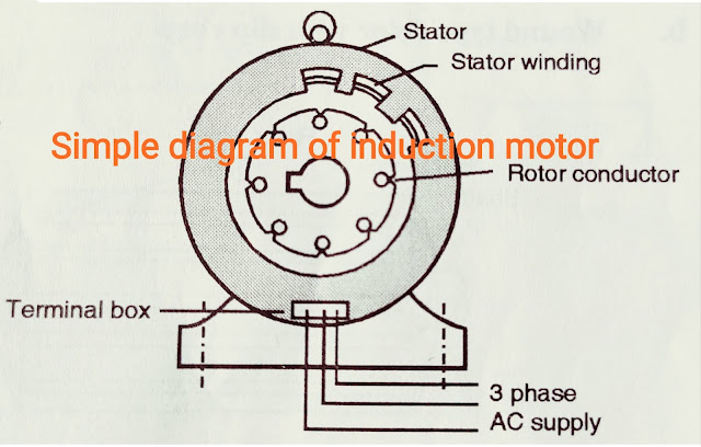
Schematic representation of 3 phase induction motor:
1). Squirrel cage type


2). Slip-ring type

- In the early discussion it is pointed out that the rotor slots are not usually parallel to the shaft but are purposely given skew shape.
Following are the advantages of the skew-shape:
1. The magnetic-hum is reduced and motor starts running quitely.
2. The general tendency is that, due to magnetic attraction, the rotor teeth remain
under stator teeth. Thus, due this magnetic locking effect the rotor may not start satisfactorily. Due to the skew shape this tendency is minimised.
There are some slight draw-backs of skew shaping:
1. Due to slight increased length of the rotor bars the rotor resistance increased slightly.
2. There is a slight increase in the machine impedance at the given slip.


Comments
Post a Comment